Signal Squishing Circuit for Temperature Monitoring System
(Winter 2018)
Background
While developing the control electronics for Aztec Electric Racing 2018 vehicle, two months before the team was schedule to leave for Lincoln, Nebraska, we found that the temperature monitoring built into our off-shelf Battery Management System (BMS) was insufficient. Competition rules required 30% of individual cells be monitored (216 cells at minimum,) although competition judge suggestions and our own FMEA analysis pointed toward greater coverage than the minimum. The BMS on hand could only monitor 15 sensors in total, necessitating a custom temperature monitoring system design. Disclaimer for anyone developing a BMS for FSAE- This is not FSAE rules compliant -- At technical inspection, you must be able to show actual temperatures within the pack through an isolated interface.
- If temperature sensor isolation fails and sensors become HV-referenced, tying common nets together on a PCB allows for a failure mode where battery cells at different potentials can short together.
Although the system design is suboptimal (dangerous), the signal squishing circuit is cute.
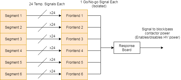
How to discard 23/24th's of your dataThe first iteration of AER's system took 24 signals from each of six segments within the high-voltage battery and used a "signal squishing" circuit to extract only the highest voltage (corresponding to highest temperature.)


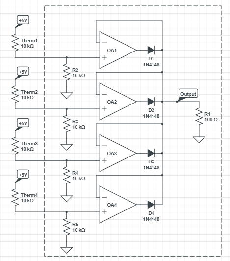
Shown are four of the 24 thermistor/precision rectifier pairs implemented on each board. A signal is generated from the thermistor by using it as the first resistor in a voltage divider -- As the temperature increases, the NTC thermistor resistance decreases and the output voltage signal increases.
The op-amps are configured essentially as voltage follower/buffers, and by taking the feedback from after the diodes, each amplifier 'overdrives' the signal to compensate for the diode drop. Any amplifier which sees a feedback voltage larger than its input signal will drive its output to ground (in single-supply operation) -- The output will no longer cause its diode to conduct, and the highest voltage of any amplifier "wins" while the diodes prevent the other 23 amplifiers from sinking current.
Original system designs flirted with isolating each signal to the low-voltage vehicle domain, but with two months before the competition and a few dozen other subsystems to pull together, the system went forward by comparing the "winning" signal against a temperature limit reference voltage and translating this into a "Go/No-go" signal (isolated by use of an electromechanical relay) to signal an overtemperature condition to the rest of the vehicle.